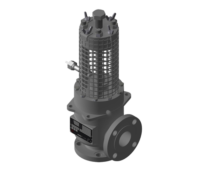
BPCV™
バックリングピン共通バルブ-入口/出口圧力同配管設計
性能
お問い合わせはこちらから
Set Pressures
BPCV™ Capabilities| Inlet Size | Outlet Size | Flow Area | Orifice (Designator) Diameter | Set Pressure Range | Media |
| 1 NPS | 1 NPS | 0.72 sq in | 0.957 in | 2100 – 3500 psi | Gas / Liquid |
| 0.86 sq in | 1.046 in | 50 – 2100 psi | Gas / Liquid | ||
| 1.5 NPS | 1.5 NPS | 2.04 sq in | 1.612 in | 15 – 1440 psi | Gas / Liquid |
| 2 NPS | 2 NPS | 3.36 sq in | 2.067 in | 15 – 720 psi | Gas / Liquid |
| 3 NPS | 3 NPS | 7.39 sq in | 3.067 in | 15 – 720 psi | Gas / Liquid |
| 4 NPS | 4 NPS | 12.73 sq in | 4.026 in | 15 – 720 psi | Gas / Liquid |
| 6 NPS | 6 NPS | 28.89 sq in | 6.065 in | 15 – 275 psi | Gas / Liquid |
| 8 NPS | 8 NPS | 50.03 sq in | 7.981 in | 15 – 275 psi | Gas / Liquid |
| 10 NPS | 10 NPS | 78.58 sq in | 10.020 in | 15 – 275 psi | Gas / Liquid |
| 12 NPS | 12 NPS | 113.10 sq in | 11.938 in | 15 – 275 psi | Gas / Liquid |
| 14 NPS | 14 NPS | 137.89 sq in | 13.124 in | 15 – 275 psi | Gas / Liquid |
Burst Tolerance
| Marked Burst Pressure | Burst Tolerance |
|---|---|
| > 40 psig (> 2.7 barg) | ± 5% |
| < 40 psig (> 2.7 barg) | ± 2 psi |
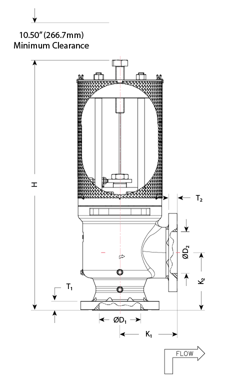
Dimensions
| Size | ØD1 | K1 | K2 | T1 | H (approx.) | W1 (approx.) | W2 (approx.) | ØD2 | T2 | Weight (approx.) | ||||||||||
| in | mm | in | mm | in | mm | in | mm | in | mm | in | mm | in | mm | in | mm | in | mm | in | mm | lbs |
|---|---|---|---|---|---|---|---|---|---|---|---|---|---|---|---|---|---|---|---|---|
| 1 x 1 | 25×25 | 1.05 | 26.7 | 3.69 | 93.7 | 3.69 | 93.7 | 0.688 | 17.5 | 20 | 508 | 8.21 | 208.5 | 6.5 | 165.1 | 1.05 | 26.7 | 0.688 | 17.5 | 50 |
| 1.5 x 1.5 | 40×40 | 1.61 | 40.9 | 4.69 | 119.1 | 4.69 | 119.1 | 0.813 | 20.6 | 22 | 558.8 | 9.34 | 237.2 | 8 | 203.2 | 1.61 | 40.9 | 0.813 | 20.6 | 80 |
| 2 x 2 | 50×50 | 2.07 | 52.5 | 5 | 127 | 5 | 127 | 0.88 | 22.3 | 22.2 | 563.8 | 9.52 | 241.8 | 8.6 | 218.44 | 2.07 | 52.5 | 0.88 | 22.3 | 85 |
| 3 x 3 | 75×75 | 3.07 | 77.98 | 6.13 | 155.7 | 6.13 | 155.7 | 1.18 | 29.9 | 31 | 787.4 | 11.1 | 331.4 | 10.96 | 278.3 | 3.07 | 77.98 | 1.18 | 19.9 | 200 |
| 4 x 4 | 100×100 | 4.03 | 102.4 | 7.12 | 180.8 | 7.12 | 180.8 | 1.25 | 31.7 | 37.1 | 942.3 | 12.34 | 313.4 | 12.55 | 318.7 | 4.03 | 102.4 | 1.25 | 31.7 | 310 |
| 6 x 6 | 150×150 | 6.07 | 154.2 | 9.12 | 231.6 | 9.12 | 231.6 | 1.5 | 38.1 | 49.9 | 1267.4 | 16.64 | 422.6 | 16.14 | 410 | 6.07 | 154.2 | 1.5 | 38.1 | 610 |
| 8 x 8 | 200×200 | 7.98 | 202.7 | 11 | 279.4 | 11 | 279.4 | 1.68 | 42.6 | 58 | 1473.2 | 19.25 | 489 | 18.69 | 474.7 | 7.98 | 202.7 | 1.68 | 42.6 | 875 |
| 10 x 10 | 250×250 | 10.02 | 254.5 | 12.5 | 317.5 | 12.5 | 317.5 | 1.93 | 49 | 64 | 1625.6 | 23.28 | 591.3 | 22.27 | 565.6 | 10.02 | 254.5 | 1.93 | 49 | 1600 |
| 12 x 12 | 300×300 | 12 | 304.8 | 14.5 | 368.3 | 14.5 | 368.3 | 2.06 | 52.32 | 70 | 1778 | 26.28 | 667.5 | 23.78 | 604 | 12 | 304.8 | 2.06 | 52.32 | 2200 |
| 14 x 14 | 350×350 | 13.25 | 336.6 | 16 | 406.4 | 16 | 406.4 | 2.18 | 71.1 | 72 | 1828.8 | 29.77 | 756.1 | 27.75 | 704.8 | 13.25 | 336.6 | 2.18 | 71.1 | 3515 |
Materials of Construction
Minimum Standard Materials| Carbon Steel | Stainless Steel | Low Temp Carbon Steel | |
|---|---|---|---|
| Body | ✓ | ✓ | ✓ |
| Disc and Spindle (Internals) | ✓ |
Accessories
BS&B supplies many of the accessories required to safely and conveniently install our overpressure relief devices and complementary products. Through our professional team and global network of sales engineers and procurement personnel, we are able to provide the highest quality accessory products to meet your installation requirements.
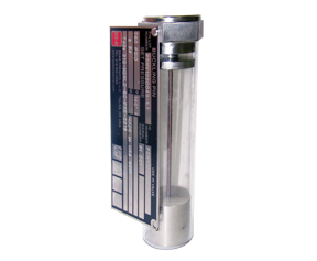
Saf-T-Pin™ Buckling Pin Cartridge
The BPAV can be provided with buckling pin cartridges that are installed like an electrical fuse. The Saf-T-Pin buckling pin cartridge allows a “quick-change” option of buckling pins with a simple push-in/pull-out design for installation within the enclosure. Each Saf-T-Pin cartridge contains a calibrated buckling pin that is perfectly mounted for optimum performance.
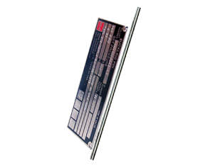
Replacement Buckling Pins
Stainless steel pins with tags containing pressure and traceability information including the serial number of the BPAV device.
Product Literature

Installations

Set Pressures
BPCV™ Capabilities| Inlet Size | Outlet Size | Flow Area | Orifice (Designator) Diameter | Set Pressure Range | Media |
| 1 NPS | 1 NPS | 0.72 sq in | 0.957 in | 2100 – 3500 psi | Gas / Liquid |
| 0.86 sq in | 1.046 in | 50 – 2100 psi | Gas / Liquid | ||
| 1.5 NPS | 1.5 NPS | 2.04 sq in | 1.612 in | 15 – 1440 psi | Gas / Liquid |
| 2 NPS | 2 NPS | 3.36 sq in | 2.067 in | 15 – 720 psi | Gas / Liquid |
| 3 NPS | 3 NPS | 7.39 sq in | 3.067 in | 15 – 720 psi | Gas / Liquid |
| 4 NPS | 4 NPS | 12.73 sq in | 4.026 in | 15 – 720 psi | Gas / Liquid |
| 6 NPS | 6 NPS | 28.89 sq in | 6.065 in | 15 – 275 psi | Gas / Liquid |
| 8 NPS | 8 NPS | 50.03 sq in | 7.981 in | 15 – 275 psi | Gas / Liquid |
| 10 NPS | 10 NPS | 78.58 sq in | 10.020 in | 15 – 275 psi | Gas / Liquid |
| 12 NPS | 12 NPS | 113.10 sq in | 11.938 in | 15 – 275 psi | Gas / Liquid |
| 14 NPS | 14 NPS | 137.89 sq in | 13.124 in | 15 – 275 psi | Gas / Liquid |
Burst Tolerance
| Marked Burst Pressure | Burst Tolerance |
|---|---|
| > 40 psig (> 2.7 barg) | ± 5% |
| < 40 psig (> 2.7 barg) | ± 2 psi |
Dimensions
| Size | ØD1 | K1 | K2 | T1 | H (approx.) | W1 (approx.) | W2 (approx.) | ØD2 | T2 | Weight (approx.) | ||||||||||
| in | mm | in | mm | in | mm | in | mm | in | mm | in | mm | in | mm | in | mm | in | mm | in | mm | lbs |
|---|---|---|---|---|---|---|---|---|---|---|---|---|---|---|---|---|---|---|---|---|
| 1 x 1 | 25×25 | 1.05 | 26.7 | 3.69 | 93.7 | 3.69 | 93.7 | 0.688 | 17.5 | 20 | 508 | 8.21 | 208.5 | 6.5 | 165.1 | 1.05 | 26.7 | 0.688 | 17.5 | 50 |
| 1.5 x 1.5 | 40×40 | 1.61 | 40.9 | 4.69 | 119.1 | 4.69 | 119.1 | 0.813 | 20.6 | 22 | 558.8 | 9.34 | 237.2 | 8 | 203.2 | 1.61 | 40.9 | 0.813 | 20.6 | 80 |
| 2 x 2 | 50×50 | 2.07 | 52.5 | 5 | 127 | 5 | 127 | 0.88 | 22.3 | 22.2 | 563.8 | 9.52 | 241.8 | 8.6 | 218.44 | 2.07 | 52.5 | 0.88 | 22.3 | 85 |
| 3 x 3 | 75×75 | 3.07 | 77.98 | 6.13 | 155.7 | 6.13 | 155.7 | 1.18 | 29.9 | 31 | 787.4 | 11.1 | 331.4 | 10.96 | 278.3 | 3.07 | 77.98 | 1.18 | 19.9 | 200 |
| 4 x 4 | 100×100 | 4.03 | 102.4 | 7.12 | 180.8 | 7.12 | 180.8 | 1.25 | 31.7 | 37.1 | 942.3 | 12.34 | 313.4 | 12.55 | 318.7 | 4.03 | 102.4 | 1.25 | 31.7 | 310 |
| 6 x 6 | 150×150 | 6.07 | 154.2 | 9.12 | 231.6 | 9.12 | 231.6 | 1.5 | 38.1 | 49.9 | 1267.4 | 16.64 | 422.6 | 16.14 | 410 | 6.07 | 154.2 | 1.5 | 38.1 | 610 |
| 8 x 8 | 200×200 | 7.98 | 202.7 | 11 | 279.4 | 11 | 279.4 | 1.68 | 42.6 | 58 | 1473.2 | 19.25 | 489 | 18.69 | 474.7 | 7.98 | 202.7 | 1.68 | 42.6 | 875 |
| 10 x 10 | 250×250 | 10.02 | 254.5 | 12.5 | 317.5 | 12.5 | 317.5 | 1.93 | 49 | 64 | 1625.6 | 23.28 | 591.3 | 22.27 | 565.6 | 10.02 | 254.5 | 1.93 | 49 | 1600 |
| 12 x 12 | 300×300 | 12 | 304.8 | 14.5 | 368.3 | 14.5 | 368.3 | 2.06 | 52.32 | 70 | 1778 | 26.28 | 667.5 | 23.78 | 604 | 12 | 304.8 | 2.06 | 52.32 | 2200 |
| 14 x 14 | 350×350 | 13.25 | 336.6 | 16 | 406.4 | 16 | 406.4 | 2.18 | 71.1 | 72 | 1828.8 | 29.77 | 756.1 | 27.75 | 704.8 | 13.25 | 336.6 | 2.18 | 71.1 | 3515 |
Materials of Construction
Minimum Standard Materials| Carbon Steel | Stainless Steel | Low Temp Carbon Steel | |
|---|---|---|---|
| Body | ✓ | ✓ | ✓ |
| Disc and Spindle (Internals) | ✓ |
Accessories
BS&B supplies many of the accessories required to safely and conveniently install our overpressure relief devices and complementary products. Through our professional team and global network of sales engineers and procurement personnel, we are able to provide the highest quality accessory products to meet your installation requirements.
Saf-T-Pin™ Buckling Pin Cartridge
The BPAV can be provided with buckling pin cartridges that are installed like an electrical fuse. The Saf-T-Pin buckling pin cartridge allows a “quick-change” option of buckling pins with a simple push-in/pull-out design for installation within the enclosure. Each Saf-T-Pin cartridge contains a calibrated buckling pin that is perfectly mounted for optimum performance.
Replacement Buckling Pins
Stainless steel pins with tags containing pressure and traceability information including the serial number of the BPAV device.