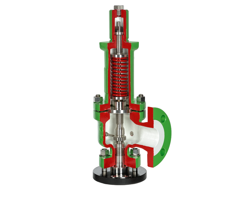
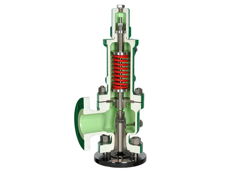
6400™
6400シリーズの安全弁はAPI526標準配管設計です
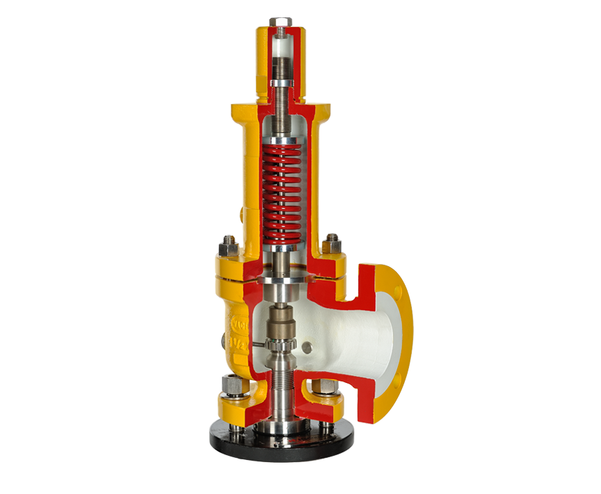
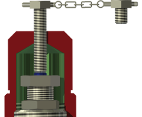
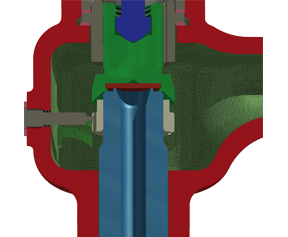
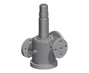
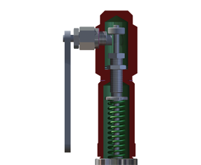
Liquid Conventional
Gas Bellows
Gas Conventional
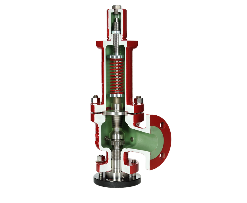
Gas Bellows
Liquid Bellows
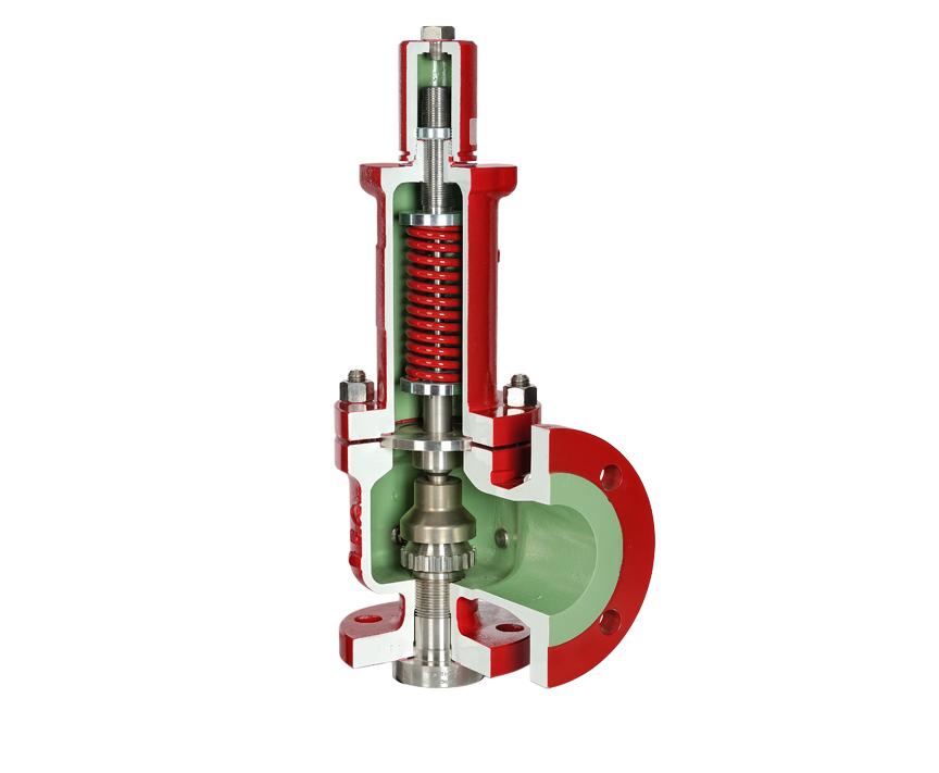
Liquid Conventional
性能
お問い合わせはこちらから
Set Pressures
6400™ Capabilities
| Inlet Size | Outlet Size | Flow Area | Orifice (Designator) Diameter | Lift | Set Pressure Range | Media |
| 1 – 1.5 NPS | 2, 3 NPS | 0.122 sq in | [D] 0.394 in | 0.157 in | 15-6004 psi | Air |
| 1 – 1.5 NPS | 2, 3 NPS | 0.122 sq in | [D] 0.394 in | 0.157 in | 15-2900 psi | Steam |
| 1 – 1.5 NPS | 2, 3 NPS | 0.222 sq in | [E] 0.531 in | 0.157 in | 15-6004 psi | Air |
| 1 – 1.5 NPS | 2, 3 NPS | 0.222 sq in | [E] 0.531 in | 0.157 in | 15-2900 psi | Steam |
| 1.5 NPS | 2, 3 NPS | 0.352 sq in | [F] 0.669 in | 0.276 in | 15-5003 psi | Air |
| 1.5 NPS | 2, 3 NPS | 0.352 sq in | [F] 0.669 in | 0.276 in | 15-2900 psi | Steam |
| 1.5 – 2 NPS | 3 NPS | 0.563 sq in | [G] 0.846 in | 0.354 in | 15-3698 psi | Air |
| 1.5 – 2 NPS | 3 NPS | 0.563 sq in | [G] 0.846 in | 0.354 in | 15-2900 psi | Steam |
| 1.5 – 2 NPS | 3 NPS | 0.887 sq in | [H] 1.063 in | 0.433 in | 15-2755 psi | Air |
| 1.5 – 2 NPS | 3 NPS | 0.887 sq in | [H] 1.063 in | 0.433 in | 15-2775 psi | Steam |
| 2 – 3 NPS | 3, 4 NPS | 1.407 sq in | [J] 1.339 in | 0.512 in | 15-2697 psi | Air |
| 2 – 3 NPS | 3, 4 NPS | 1.407 sq in | [J] 1.339 in | 0.512 in | 15-2697 psi | Steam |
| 3 NPS | 4, 6 NPS | 2.046 sq in | [K] 1.614 in | 0.551 in | 15-2219 psi | Air |
| 3 NPS | 4, 6 NPS | 2.046 sq in | [K] 1.614 in | 0.551 in | 15-2219 psi | Steam |
| 3 – 4 NPS | 4, 6 NPS | 3.166 sq in | [L] 2.008 in | 0.63 in | 15-1494 psi | Air |
| 3 – 4 NPS | 4, 6 NPS | 3.166 sq in | [L] 2.008 in | 0.63 in | 15-1494 psi | Steam |
| 4 NPS | 6 NPS | 4.025 sq in | [M] 2.264 in | 0.748 in | 15-1102 psi | Air |
| 4 NPS | 6 NPS | 4.025 sq in | [M] 2.264 in | 0.748 in | 15-1102 psi | Steam |
| 4 NPS | 6 NPS | 4.986 sq in | [N] 2.52 in | 0.787 in | 15-1001 psi | Air |
| 4 NPS | 6 NPS | 4.986 sq in | [N] 2.52 in | 0.787 in | 15-1001 psi | Steam |
| 4 NPS | 6 NPS | 7.218 sq in | [P] 3.031 in | 0.945 in | 15-1001 psi | Air |
| 4 NPS | 6 NPS | 7.218 sq in | [P] 3.031 in | 0.945 in | 15-1001 psi | Steam |
| 6 NPS | 8 NPS | 12.174 sq in | [Q] 3.937 in | 1.181 in | 15-595 psi | Air |
| 6 NPS | 8 NPS | 12.174 sq in | [Q] 3.937 in | 1.181 in | 15-595 psi | Steam |
| 6 NPS | 8, 10 NPS | 17.53 sq in | [R] 4.724 in | 1.339 in | 15-305 psi | Air |
| 6 NPS | 8, 10 NPS | 17.53 sq in | [R] 4.724 in | 1.339 in | 15-305 psi | Steam |
| 8 NPS | 10 NPS | 28.497 sq in | [T] 6.024 in | 1.654 in | 15-305 psi | Air |
| 8 NPS | 10 NPS | 28.497 sq in | [T] 6.024 in | 1.654 in | 15-305 psi | Steam |
| Inlet Size | Outlet Size | Flow Area | Orifice (Designator) Diameter | Lift | Set Pressure Range | Media |
| 1 – 1.5 NPS | 2, 3 NPS | 0.122 sq in | [D] 0.394 in | 0.071 in | 15-6004 psi | Water |
| 1 – 1.5 NPS | 2, 3 NPS | 0.222 sq in | [E] 0.531 in | 0.209 in | 15-6004 psi | Water |
| 1.5 NPS | 2, 3 NPS | 0.362 sq in | [F] 0.669 in | 0.26 in | 15-5003 psi | Water |
| 1.5 – 2 NPS | 3 NPS | 0.563 sq in | [G] 0.846 in | 0.394 in | 15-3698 psi | Water |
| 1.5 – 2 NPS | 3 NPS | 0.887 sq in | [H] 1.063 in | 0.512 in | 15-2755 psi | Water |
| 2 – 3 NPS | 3, 4 NPS | 1.407 sq in | [J] 1.338 in | 0.551 in | 15-2697 psi | Water |
| 3 NPS | 4, 6 NPS | 2.046 sq in | [K] 1.614 in | 0.63 in | 15-2219 psi | Water |
| 3 – 4 NPS | 4, 6 NPS | 3.166 sq in | [L] 2.008 in | 0.787 in | 15-1494 psi | Water |
| 4 NPS | 6 NPS | 4.025 sq in | [M] 2.264 in | 0.866 in | 15-1102 psi | Water |
| 4 NPS | 6 NPS | 4.986 sq in | [N] 2.52 in | 0.906 in | 15-1001 psi | Water |
| 4 NPS | 6 NPS | 7.218 sq in | [P] 3.031 in | 1.102 in | 15-1001 psi | Water |
| 6 NPS | 8 NPS | 12.174 sq in | [Q] 3.937 in | 1.22 in | 15-595 psi | Water |
| 6 NPS | 8, 10 NPS | 17.53 sq in | [R] 4.724 in | 1.535 in | 15-305 psi | Water |
| 8 NPS | 10 NPS | 28.497 sq in | [T] 6.024 in | 1.929 in | 15-305 psi | Water |
Materials of Construction
Minimum Standard Materials| Carbon Steel | Stainless Steel | Low Temp Carbon Steel | |
|---|---|---|---|
| Body | ✓ | ✓ | ✓ |
| Disc and Spindle (Internals) | ✓ |
Alternative Materials availabile upon request, e.g Inconel 625, Duplex, Supler Duplex
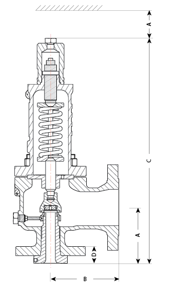
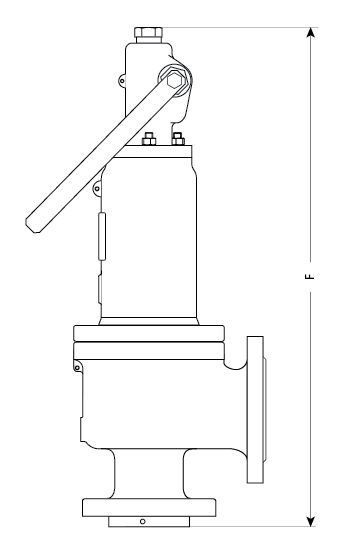
Dimensions*
| Orifice API 526 | Rating | Inlet Size | Outlet Size | Flow Area | General Dimensions | Standard | Lever | |||||
| in2 | A | B | C | D | E | F | Weight – (lbs) | |||||
|---|---|---|---|---|---|---|---|---|---|---|---|---|
| D | 150 x 150 | 1 | 2 | 0.12 | 4.13 | 4.49 | 16.61 | 1.14 | 3.54 | 19.29 | 35.3 | 37.5 |
| 300L x 150 | ||||||||||||
| 300 x 150 | 1.26 | |||||||||||
| 600 x 150 | 1.34 | |||||||||||
| 900 x 300 | 1.5 | 2 | 5.51 | 19.37 | 1.73 | 21.89 | 68.3 | 72.8 | ||||
| 1500 x 300 | ||||||||||||
| 2500 x 300 | 1.5 | 3 | 5.51 | 7.01 | 20.39 | 2.36 | 22.91 | 86.0 | 90.4 | |||
| E | 150 x 150 | 1 | 2 | 0.22 | 4.13 | 4.49 | 16.61 | 1.14 | 3.54 | 19.29 | 35.3 | 37.5 |
| 300L x 150 | ||||||||||||
| 300 x 150 | 1.26 | |||||||||||
| 600 x 150 | 1.34 | |||||||||||
| 900 x 300 | 1.5 | 2 | 5.51 | 19.37 | 1.73 | 21.89 | 68.3 | 72.8 | ||||
| 1500 x 300 | ||||||||||||
| 2500 x 300 | 1.5 | 3 | 5.51 | 7.01 | 20.39 | 2.36 | 22.91 | 86.0 | 90.4 | |||
* Displayed here is a particle table. Click here to see complete table.
Accessories
Test-Gag
O-Ring
Heating Jacket
Lever


Set Pressures
6400™ Capabilities
| Inlet Size | Outlet Size | Flow Area | Orifice (Designator) Diameter | Lift | Set Pressure Range | Media |
| 1 – 1.5 NPS | 2, 3 NPS | 0.122 sq in | [D] 0.394 in | 0.157 in | 15-6004 psi | Air |
| 1 – 1.5 NPS | 2, 3 NPS | 0.122 sq in | [D] 0.394 in | 0.157 in | 15-2900 psi | Steam |
| 1 – 1.5 NPS | 2, 3 NPS | 0.222 sq in | [E] 0.531 in | 0.157 in | 15-6004 psi | Air |
| 1 – 1.5 NPS | 2, 3 NPS | 0.222 sq in | [E] 0.531 in | 0.157 in | 15-2900 psi | Steam |
| 1.5 NPS | 2, 3 NPS | 0.352 sq in | [F] 0.669 in | 0.276 in | 15-5003 psi | Air |
| 1.5 NPS | 2, 3 NPS | 0.352 sq in | [F] 0.669 in | 0.276 in | 15-2900 psi | Steam |
| 1.5 – 2 NPS | 3 NPS | 0.563 sq in | [G] 0.846 in | 0.354 in | 15-3698 psi | Air |
| 1.5 – 2 NPS | 3 NPS | 0.563 sq in | [G] 0.846 in | 0.354 in | 15-2900 psi | Steam |
| 1.5 – 2 NPS | 3 NPS | 0.887 sq in | [H] 1.063 in | 0.433 in | 15-2755 psi | Air |
| 1.5 – 2 NPS | 3 NPS | 0.887 sq in | [H] 1.063 in | 0.433 in | 15-2775 psi | Steam |
| 2 – 3 NPS | 3, 4 NPS | 1.407 sq in | [J] 1.339 in | 0.512 in | 15-2697 psi | Air |
| 2 – 3 NPS | 3, 4 NPS | 1.407 sq in | [J] 1.339 in | 0.512 in | 15-2697 psi | Steam |
| 3 NPS | 4, 6 NPS | 2.046 sq in | [K] 1.614 in | 0.551 in | 15-2219 psi | Air |
| 3 NPS | 4, 6 NPS | 2.046 sq in | [K] 1.614 in | 0.551 in | 15-2219 psi | Steam |
| 3 – 4 NPS | 4, 6 NPS | 3.166 sq in | [L] 2.008 in | 0.63 in | 15-1494 psi | Air |
| 3 – 4 NPS | 4, 6 NPS | 3.166 sq in | [L] 2.008 in | 0.63 in | 15-1494 psi | Steam |
| 4 NPS | 6 NPS | 4.025 sq in | [M] 2.264 in | 0.748 in | 15-1102 psi | Air |
| 4 NPS | 6 NPS | 4.025 sq in | [M] 2.264 in | 0.748 in | 15-1102 psi | Steam |
| 4 NPS | 6 NPS | 4.986 sq in | [N] 2.52 in | 0.787 in | 15-1001 psi | Air |
| 4 NPS | 6 NPS | 4.986 sq in | [N] 2.52 in | 0.787 in | 15-1001 psi | Steam |
| 4 NPS | 6 NPS | 7.218 sq in | [P] 3.031 in | 0.945 in | 15-1001 psi | Air |
| 4 NPS | 6 NPS | 7.218 sq in | [P] 3.031 in | 0.945 in | 15-1001 psi | Steam |
| 6 NPS | 8 NPS | 12.174 sq in | [Q] 3.937 in | 1.181 in | 15-595 psi | Air |
| 6 NPS | 8 NPS | 12.174 sq in | [Q] 3.937 in | 1.181 in | 15-595 psi | Steam |
| 6 NPS | 8, 10 NPS | 17.53 sq in | [R] 4.724 in | 1.339 in | 15-305 psi | Air |
| 6 NPS | 8, 10 NPS | 17.53 sq in | [R] 4.724 in | 1.339 in | 15-305 psi | Steam |
| 8 NPS | 10 NPS | 28.497 sq in | [T] 6.024 in | 1.654 in | 15-305 psi | Air |
| 8 NPS | 10 NPS | 28.497 sq in | [T] 6.024 in | 1.654 in | 15-305 psi | Steam |
| Inlet Size | Outlet Size | Flow Area | Orifice (Designator) Diameter | Lift | Set Pressure Range | Media |
| 1 – 1.5 NPS | 2, 3 NPS | 0.122 sq in | [D] 0.394 in | 0.071 in | 15-6004 psi | Water |
| 1 – 1.5 NPS | 2, 3 NPS | 0.222 sq in | [E] 0.531 in | 0.209 in | 15-6004 psi | Water |
| 1.5 NPS | 2, 3 NPS | 0.362 sq in | [F] 0.669 in | 0.26 in | 15-5003 psi | Water |
| 1.5 – 2 NPS | 3 NPS | 0.563 sq in | [G] 0.846 in | 0.394 in | 15-3698 psi | Water |
| 1.5 – 2 NPS | 3 NPS | 0.887 sq in | [H] 1.063 in | 0.512 in | 15-2755 psi | Water |
| 2 – 3 NPS | 3, 4 NPS | 1.407 sq in | [J] 1.338 in | 0.551 in | 15-2697 psi | Water |
| 3 NPS | 4, 6 NPS | 2.046 sq in | [K] 1.614 in | 0.63 in | 15-2219 psi | Water |
| 3 – 4 NPS | 4, 6 NPS | 3.166 sq in | [L] 2.008 in | 0.787 in | 15-1494 psi | Water |
| 4 NPS | 6 NPS | 4.025 sq in | [M] 2.264 in | 0.866 in | 15-1102 psi | Water |
| 4 NPS | 6 NPS | 4.986 sq in | [N] 2.52 in | 0.906 in | 15-1001 psi | Water |
| 4 NPS | 6 NPS | 7.218 sq in | [P] 3.031 in | 1.102 in | 15-1001 psi | Water |
| 6 NPS | 8 NPS | 12.174 sq in | [Q] 3.937 in | 1.22 in | 15-595 psi | Water |
| 6 NPS | 8, 10 NPS | 17.53 sq in | [R] 4.724 in | 1.535 in | 15-305 psi | Water |
| 8 NPS | 10 NPS | 28.497 sq in | [T] 6.024 in | 1.929 in | 15-305 psi | Water |
Materials of Construction
Minimum Standard Materials| Carbon Steel | Stainless Steel | Low Temp Carbon Steel | |
|---|---|---|---|
| Body | ✓ | ✓ | ✓ |
| Disc and Spindle (Internals) | ✓ |
Alternative Materials availabile upon request, e.g Inconel 625, Duplex, Supler Duplex
Dimensions*
| Orifice API 526 | Rating | Inlet Size | Outlet Size | Flow Area | General Dimensions | Standard | Lever | |||||
| in2 | A | B | C | D | E | F | Weight – (lbs) | |||||
|---|---|---|---|---|---|---|---|---|---|---|---|---|
| D | 150 x 150 | 1 | 2 | 0.12 | 4.13 | 4.49 | 16.61 | 1.14 | 3.54 | 19.29 | 35.3 | 37.5 |
| 300L x 150 | ||||||||||||
| 300 x 150 | 1.26 | |||||||||||
| 600 x 150 | 1.34 | |||||||||||
| 900 x 300 | 1.5 | 2 | 5.51 | 19.37 | 1.73 | 21.89 | 68.3 | 72.8 | ||||
| 1500 x 300 | ||||||||||||
| 2500 x 300 | 1.5 | 3 | 5.51 | 7.01 | 20.39 | 2.36 | 22.91 | 86.0 | 90.4 | |||
| E | 150 x 150 | 1 | 2 | 0.22 | 4.13 | 4.49 | 16.61 | 1.14 | 3.54 | 19.29 | 35.3 | 37.5 |
| 300L x 150 | ||||||||||||
| 300 x 150 | 1.26 | |||||||||||
| 600 x 150 | 1.34 | |||||||||||
| 900 x 300 | 1.5 | 2 | 5.51 | 19.37 | 1.73 | 21.89 | 68.3 | 72.8 | ||||
| 1500 x 300 | ||||||||||||
| 2500 x 300 | 1.5 | 3 | 5.51 | 7.01 | 20.39 | 2.36 | 22.91 | 86.0 | 90.4 | |||
* Displayed here is a particle table. Click here to see complete table.
Accessories
Test-Gag
O-Ring
Heating Jacket