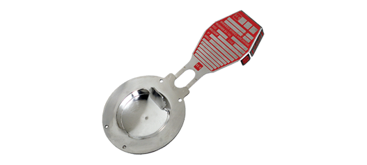
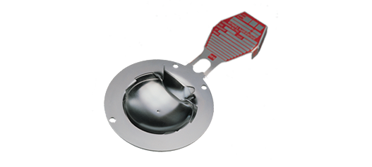
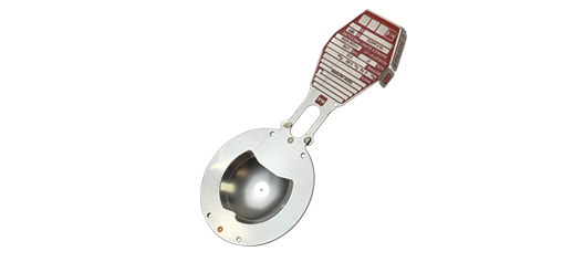
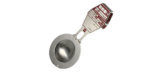
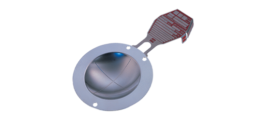
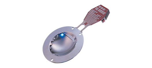
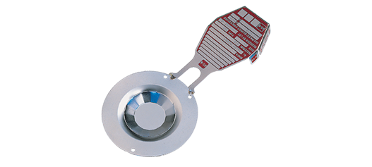
SRI-7RS™ホルダー
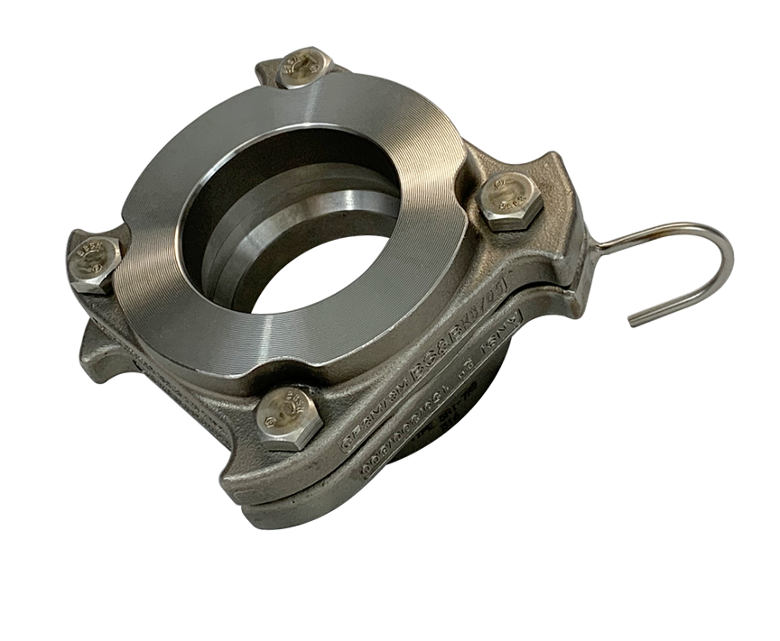
中心固定型プリトルクホルダー
性能
- フランジのボルトサークル内に収まり、取り付け、取り外しが容易なインサートタイプのホルダー
- 事前にトルクをかけられた六角ヘッドのキャップスクリューを使うため、一般的な工具で取り付け、使用中の再トルク調整が可能。高品質のステンレス鋼キャップスクリューによりホルダーのかじりを防止
- ホルダーの独自形状によりパイプとの同心性を保ち、定められたKr値で最適なフロー特性を確保します
- 破裂板の座面を広くすることによりスパイラル型ガスケットに対応するコンパニオン・フランジ・スタッドへの高トルクが可能
- J ボルトは、プロセス側フランジの外周に開けられた穴と接合することにより、ホルダーが必要な方向に確実に取り付けられるようにします。
- ホルダー内の位置決めピンが破裂板の位置決めホールと接合する事により、破裂板のセンタリングと正しい取付け方向を確保。
- セーフティヘッドの側面に刻印されているフロー矢印は、正しいフロー方向を示します
- ホルダー内側座面に独自の「バイトシール」を施しており、破裂板とホルダーのプロセス側の間のシール性を最適化し、10^-6cc/s He 以上の気密性を実現
- 入口または出口のいずれかにオプションでタップ追加工が可能で、監視デバイスやセンサーの設置が可能
- フランジ付き配管接続に使用。レイズドフェイス、リングジョイント、その他複数のフランジ定格および配管規格に対応した設計
- ラプチャーディスクのドーム部は、配管システムに設置される際の損傷を避けるため、ホルダー内で完全に保護されています
お問い合わせはこちらから
Sizes & Pressures

| Disk Size | Safety Head Flange Rating | Safety Head Flange Thickness | ||||
| in | mm | ASME / ANSI | EN | JIS | in | mm |
|---|---|---|---|---|---|---|
| 1 | 25 | 150/300/600 | 10/16/25/40 | 10/16/20/30/40 | 1.5 | 38 |
| 1.5 | 40 | 150/300/600 | 10/16/25/40 | 10/16/20/30/40 | 1.7 | 43 |
| 2 | 50 | 150/300/600 | 10/16/25/40 | 10/16/20/30/40 | 1.9 | 48 |
| 3 | 80 | 150/300/600 | 10/16/25/40 | 16/20/30/40 | 2.2 | 55 |
| 4 | 100 | 150/300* | 10/16/25/40 | 16/20/30/40 | 2.9 | 73 |
| 6 | 150 | 150/300* | 10/16/25/40 | 10/16/20/30 | 3.6 | 92 |
| 8 | 200 | 150/300* | 10/16/25/40 | 16/20/30 | 3.8 | 95 |
Standard Materials
316 stainless steel and carbon steel.
Torque Resistant Safety Head Option
The Type TR™ Series torque resistant safety head option offers the identical performance and flow characteristics valued from standard BS&B safety heads. The only difference – the TR Series Safety Heads are designed with a wider seating surface to be used with metal spiral wound gaskets at the flange. This distinct safety feature protects rupture disks from situations where plant personnel may overtorque rupture disks within piping systems.
Because of the wider seating surface of the TR Series Safety Head, the load is distributed over a much broader area reducing the influence of excessive torque transmitted to the disk.
Accessories
BS&B supplies many of the accessories required to safely and conveniently install our overpressure relief devices and complementary products. Through our professional team and global network of sales engineers and procurement personnel, we are able to provide the highest quality accessory products to meet your installation requirements.
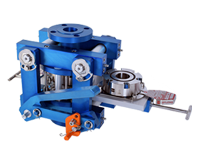
Saf-T-Change Quick Disk Replacement (QDR)
After activation, the replacement disk is quickly slid into place. Saving hours of lost production due to blown rupture disks.
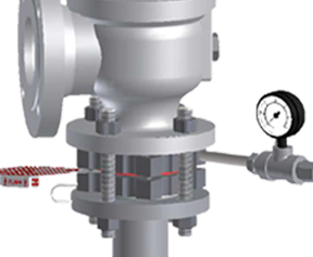
Tell-Tale Assemblies & Excess Flow Valves/Gauges
A gauge tap in the outlet flange of the safety head may be considered when the safety head is installed in a vertical position.
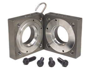
Spare Safety Heads & Cap Screws
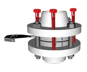
Jackscrews
When activated, the jackscrews effectively separate the flanges, providing adequate clearance to remove or insert a safety head and external gaskets.
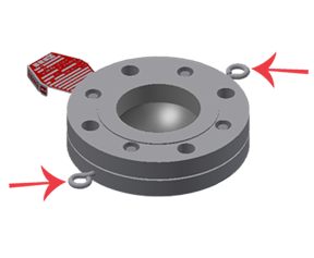
Lifting Lug Eye Bolts
Eye bolts are recommended when weight and/or accessibility is a factor in lifting safety heads.
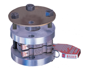
Baffle Plate
When a safety head is free-vented to atmosphere, a baffle plate may be considered to disperse overpressure and absorb recoil.
Sizes & Pressures
| Disk Size | Safety Head Flange Rating | Safety Head Flange Thickness | ||||
| in | mm | ASME / ANSI | EN | JIS | in | mm |
|---|---|---|---|---|---|---|
| 1 | 25 | 150/300/600 | 10/16/25/40 | 10/16/20/30/40 | 1.5 | 38 |
| 1.5 | 40 | 150/300/600 | 10/16/25/40 | 10/16/20/30/40 | 1.7 | 43 |
| 2 | 50 | 150/300/600 | 10/16/25/40 | 10/16/20/30/40 | 1.9 | 48 |
| 3 | 80 | 150/300/600 | 10/16/25/40 | 16/20/30/40 | 2.2 | 55 |
| 4 | 100 | 150/300* | 10/16/25/40 | 16/20/30/40 | 2.9 | 73 |
| 6 | 150 | 150/300* | 10/16/25/40 | 10/16/20/30 | 3.6 | 92 |
| 8 | 200 | 150/300* | 10/16/25/40 | 16/20/30 | 3.8 | 95 |
Standard Materials
316 stainless steel and carbon steel.
Torque Resistant Safety Head Option
The Type TR™ Series torque resistant safety head option offers the identical performance and flow characteristics valued from standard BS&B safety heads. The only difference – the TR Series Safety Heads are designed with a wider seating surface to be used with metal spiral wound gaskets at the flange. This distinct safety feature protects rupture disks from situations where plant personnel may overtorque rupture disks within piping systems.
Because of the wider seating surface of the TR Series Safety Head, the load is distributed over a much broader area reducing the influence of excessive torque transmitted to the disk.
Accessories
BS&B supplies many of the accessories required to safely and conveniently install our overpressure relief devices and complementary products. Through our professional team and global network of sales engineers and procurement personnel, we are able to provide the highest quality accessory products to meet your installation requirements.

Saf-T-Change Quick Disk Replacement (QDR)
After activation, the replacement disk is quickly slid into place. Saving hours of lost production due to blown rupture disks.

Tell-Tale Assemblies & Excess Flow Valves/Gauges
A gauge tap in the outlet flange of the safety head may be considered when the safety head is installed in a vertical position.

Spare Safety Heads & Cap Screws

Jackscrews
When activated, the jackscrews effectively separate the flanges, providing adequate clearance to remove or insert a safety head and external gaskets.

Lifting Lug Eye Bolts
Eye bolts are recommended when weight and/or accessibility is a factor in lifting safety heads.

Baffle Plate
When a safety head is free-vented to atmosphere, a baffle plate may be considered to disperse overpressure and absorb recoil.
Flange Bolt Patterns
ANSI / ASME B16.5 150lb configurations shown.
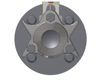
1” (DN 25) NFI-7RS
1.5” (DN 40) NFI-7RS
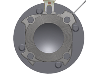
2” (DN 50) NFI-7RS
3” (DN 80) NFI-7RS
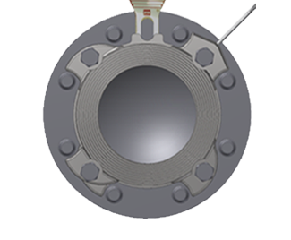
4” (DN 100) NFI-7RS
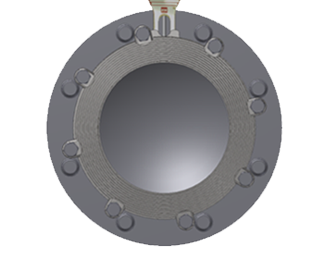
6” (DN 150) NFI-7RS
8” (DN 150) NFI-7RS
フランジボルトの種類
ANSI / ASME B16.5 150lb 構成を示しています

1” (DN 25) NFI-7RS
1.5” (DN 40) NFI-7RS

2” (DN 50) NFI-7RS
3” (DN 80) NFI-7RS

4” (DN 100) NFI-7RS


